3-Speed Planetary Transmission
Overview
With normal gears, cars only get two choices; fast acceleration, or high top speed. Transmissions fix this by offering multiple gear ratios to choose from, but they’re usually made of metal and thus, outside the scope of most DIY’ers.
With my transmission I am to change this. This is a 3D printed, clutchless, high performance planetary transmission. It can be made economically with just a 3d printer, some heated inserts, screws, bearings, and metal dowel pins. And it’s quite strong too.
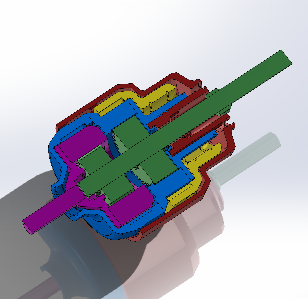
Custom Low-Friction Dog-Clutch Shifter
It’s no secret that 3D printed plastics soften with little heat, that’s why they’re 3D printable in the first place. This is bad since traditional planetary transmissions use friction clutches as couplers, which encounter frequent “micro-slips” from torque spikes that arise from torque spikes.
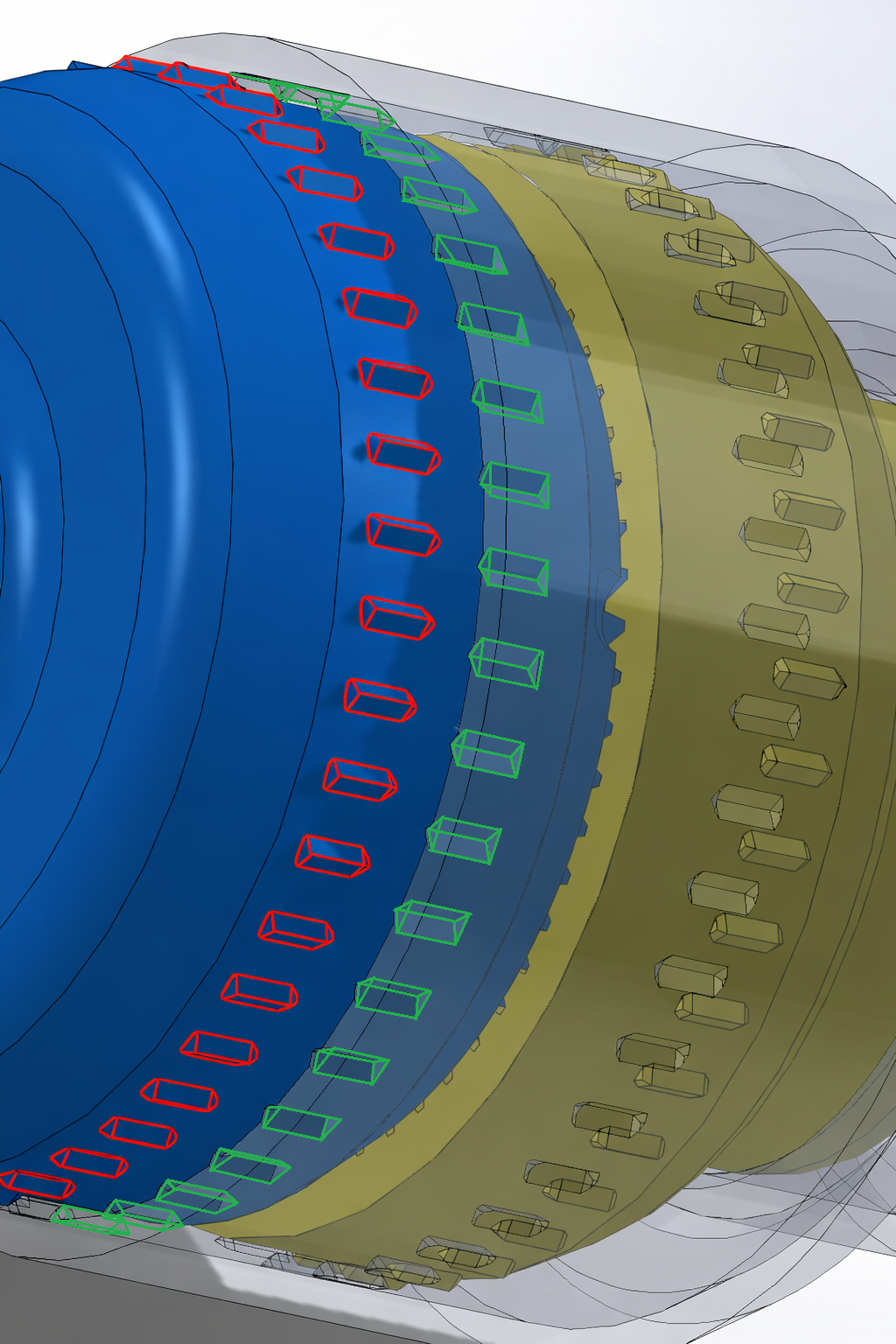
This issue is combatted by a custom “spline-clutch” mechanism that holds ring gears in place with splines attached to a sliding outer shell. Since the force from the ring gears is pushing perpendicular to the surface holding the rings in place, there’s nowhere for the ring gear to slip. The harder it pushes, the harder it digs into the surface of the dog teeth, further reducing the chance of slipping even during torque spikes.
EHeat = FFriction * Δd, so by reducing Δd through the elimination of micro slips, heat generation is greatly reduced. This theoretically reduces total deformation by 90+%, greatly extending the life of the transmission and enabling its usage with stronger engines.
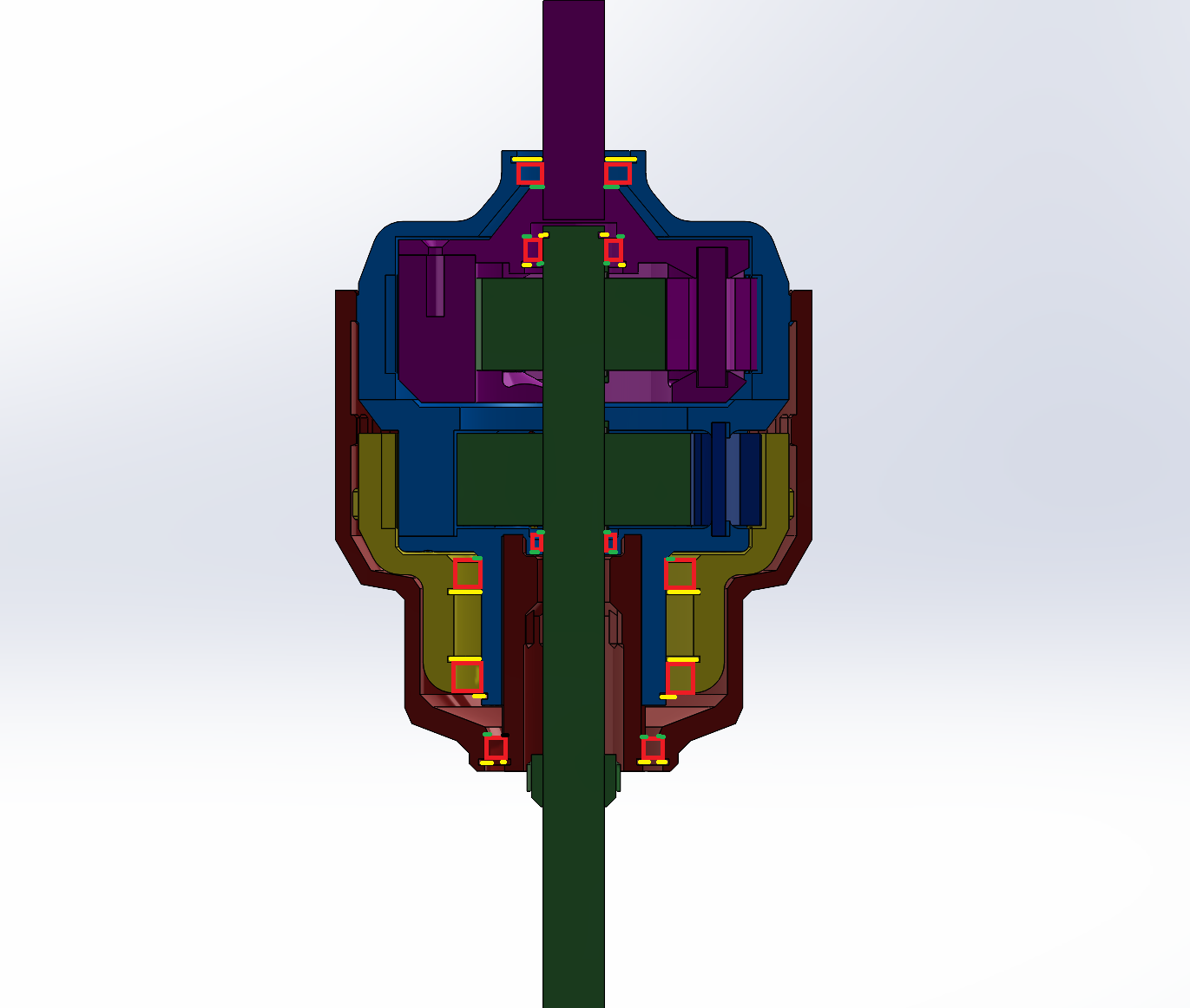
Meticulously Optimized
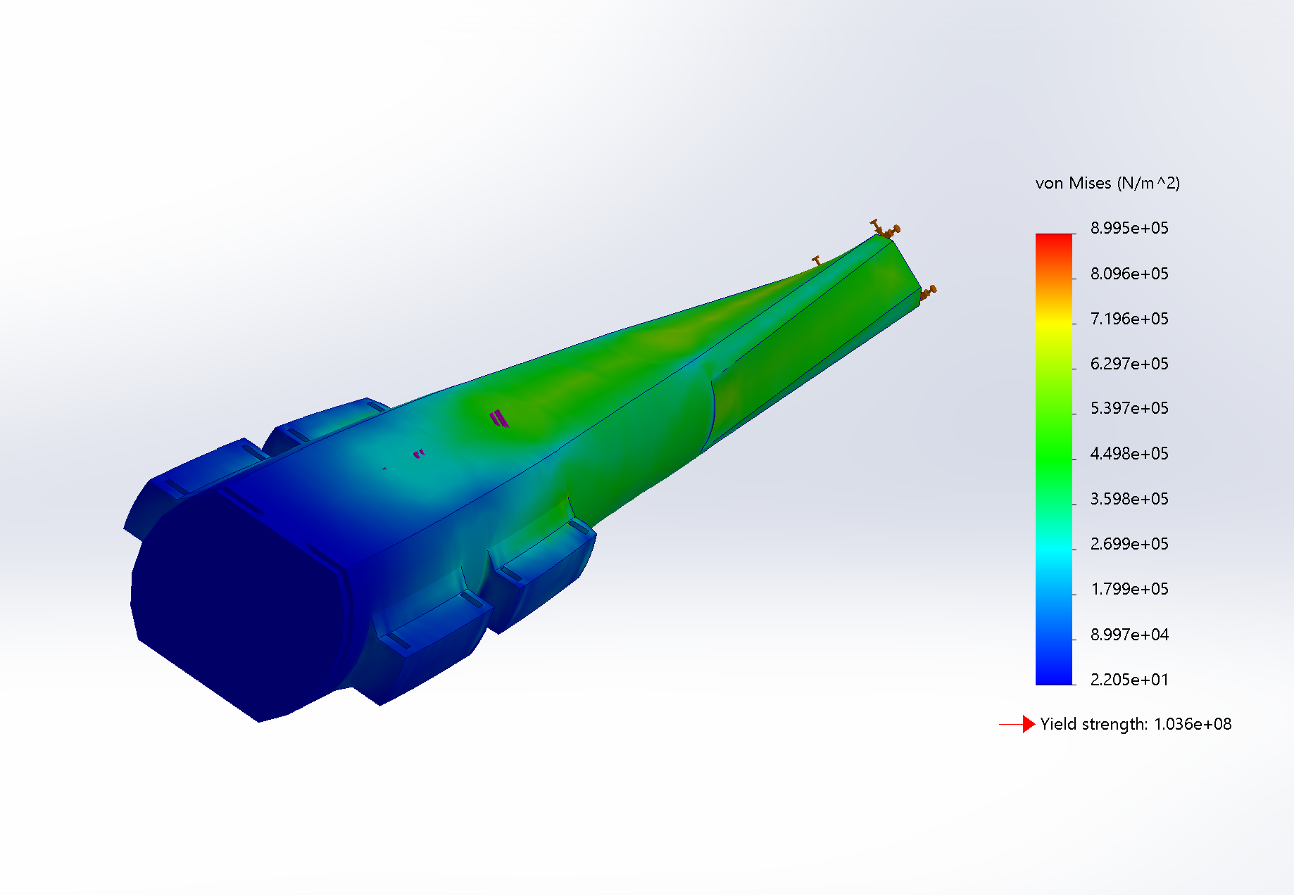
Throughout the design, several retainer rings were implemented to prevent the mechanical migration of bearings. Plastic is very prone to mechanical creep, especially at high temperatures, so a single press fit could not be trusted to permanently keep all attachments in place. Implementing said retainer rings were simple for all components save one; the driving shaft. A groove would be a weak point, and since the long driving shaft would already be prone to deformation, a weak point would be unacceptable.
Here’s the interesting part; good 3D printed shafts don’t have perfectly circular profiles. They must be printed lying down to orient the weak layer lines along the axis, and since that would cause bed adhesion issues, the top and bottom must be cut. This gave me the opportunity to create several different retainer designs and validate them using FEA to see which would be the most durable. Eventually I chose a design that protruded out from the original shaft to keep it as thick as possible. This wing design not only allowed the driving shaft to maintain its original strength, but also gave the sun gears more surface area to transfer their torque to the shaft, thereby enabling it to hold stronger loads.